OSI 7-Layer Model - Part 1

Layer stack:
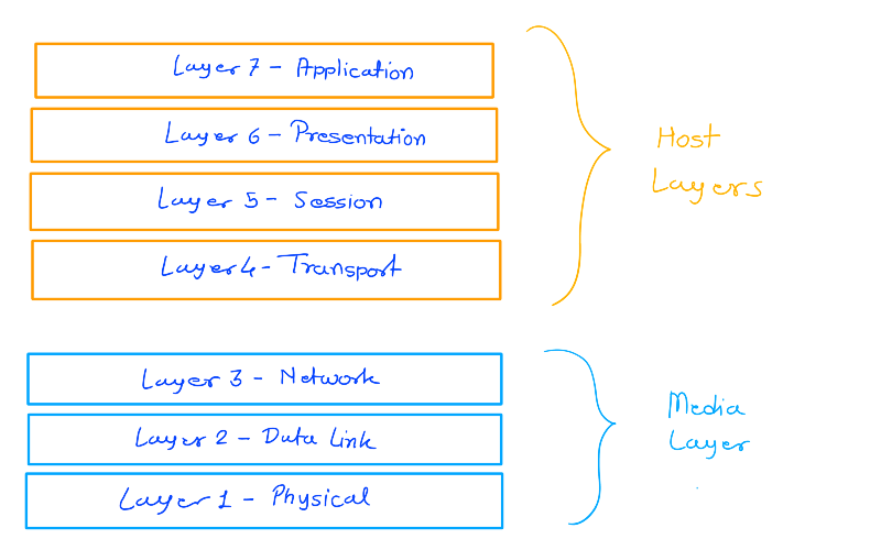
In the OSI model, the media layers are the bottom three layers, and the host layers are the top four layers. The media layers define hardware orientation, such as: Routing, Switching, Cable specifications.
The host layers define software that implements network services. The transport layer is the first of the four host layers. This layer manages the transmission of data between nodes, including:
- Ensuring that data arrives in the correct sequence
- Correcting any errors
Layer 1 - Physical
The physical layer, or layer 1, is the first and lowest layer in the OSI model of computer networking. It’s also known as the hardware layer.
Layer 1 (Physical) specifications define the transmission and reception of RAW BIT STREAMS between a device and a SHARED physical medium. It defines things like voltage levels, timing, rates, distances, modulation and connectors
The physical layer is responsible for:
- The physical connection between devices
- Data transmission over the physical medium
Physical medium can be:
- Copper (electrical)
- Fibre (light)
- WIFI (RF)
Note: Layer 1 device can only understand layer 1, and Layer 3 device understand all the layers beneath.
HUB: Connects multiple devices on physical layer, It has only one job anything received on any port is transmitted on every other port including errors and collisions.
Note: There is no individual address for the device, all data is processed by all devices. If multiple devices transmit data at once a collision occurs which will corrupt the data
L1 has no media access control and no collision detection. Because of this Layer 1 cannot scale well.
Layer 2 - Data Link
Layer 2 operates directly above Layer 1 in network communication. In this context, the data link layer plays a vital role in managing data transfer. It takes the data packets received from the network layer and dissects them into smaller units called frames. Within the data link layer, the header is crucial as it contains information about the source and destination MAC (Media Access Control) addresses. It’s here that data is converted into binary format (1s and 0s) and prepared for transmission at the physical layer.
The MAC address is a unique combination of alphanumeric characters assigned to each network card. It’s often referred to as a physical address because it’s permanently embedded in the network card, ensuring it remains constant.
One essential function of the data link layer is to enable multiple systems to share a common communication medium, known as a shared media. This is facilitated by mechanisms like CSMA/CD (Carrier Sense Multiple Access with Collision Detection).
Under CSMA/CD, when multiple devices attempt to transmit data simultaneously and a collision occurs, each device involved detects the collision. Following collision detection, these devices initiate a random waiting period before retransmitting. The likelihood of multiple devices selecting the same delay is extremely low, increasing the chances of successful data transmission during retransmission.
In modern networking, we’ve moved away from shared bus topologies to using switches, which are Layer 2 devices. Switches are equipped to intelligently direct network traffic to the appropriate destination. They achieve this by learning the MAC addresses of connected devices. When a computer connects to the network through a switch, it provides its MAC address to the switch. This way, the switch can efficiently forward data to the correct computer by referring to its MAC address.
These switches, with their ability to learn and route traffic based on MAC addresses, have greatly improved network efficiency and reduced unnecessary data transmissions.
Layer 3 - Network
Layer 3 networking, often referred to as the network layer, plays a crucial role in the process of routing data across different networks and within the same network. It’s responsible for determining the best path for data packets to travel from the source to the destination. To explain this in detail, I’ll break down the key components and processes involved, including ARP (Address Resolution Protocol), routes, route tables, routers, IP addresses with subnet masks, packet generation, and the data delivery process.
1. IP Addresses with Subnet Masks: The foundation of Layer 3 networking is the use of IP (Internet Protocol) addresses, both for the source and destination devices. IP addresses are hierarchical and structured, allowing for efficient routing of data. Subnet masks are used to divide IP addresses into network and host portions. For example, an IP address like “192.168.1.10” with a subnet mask of “255.255.255.0” indicates that the first three segments (192.168.1) represent the network, and the last segment (10) is for a specific host within that network.
2. ARP (Address Resolution Protocol): ARP is used to map an IP address to a physical MAC (Media Access Control) address on a local network. When a device needs to communicate with another device on the same network, it uses ARP to discover the MAC address associated with the target IP address.
3. Routing: Routing is the process of determining the optimal path for data packets to travel between networks. It’s like deciding the best route on a map. Routers are the devices responsible for routing. They make these decisions based on the destination IP address found in the packet header.
4. Route Tables: A router uses a route table to determine where to forward incoming packets. This table contains information about various networks and how to reach them. Each entry includes a network address, a subnet mask, the next-hop router’s IP address, and an interface through which the router can forward packets to reach the destination network.
5. Packet Generation: When a device wants to send data to another device, it generates packets. These packets contain the source and destination IP addresses, among other information, in the packet header.
Here’s a simplified ASCII diagram of an IP packet’s header:
   0                   1                   2                   3
   0 1 2 3 4 5 6 7 8 9 0 1 2 3 4 5 6 7 8 9 0 1 2 3 4 5 6 7 8 9 0 1
  +-+-+-+-+-+-+-+-+-+-+-+-+-+-+-+-+-+-+-+-+-+-+-+-+-+-+-+-+-+-+-+-+
  | Version  |    IHL   | Type of Service |      Total Length     |
  | (4 bits) | (4 bits) |    (8 bits)     |        (16 bits)      |
  +-+-+-+-+-+-+-+-+-+-+-+-+-+-+-+-+-+-+-+-+-+-+-+-+-+-+-+-+-+-+-+-+
  | Identification            |  Flags   |     Fragment Offset    |
  |     (16 bits)             | (3 bits) |        (13 bits)       |
  +-+-+-+-+-+-+-+-+-+-+-+-+-+-+-+-+-+-+-+-+-+-+-+-+-+-+-+-+-+-+-+-+
  |  Time to Live  |  Protocol     |         Header Checksum      |
  |     (8 bits)   |   (8 bits)    |          (16 bits)           |
  +-+-+-+-+-+-+-+-+-+-+-+-+-+-+-+-+-+-+-+-+-+-+-+-+-+-+-+-+-+-+-+-+
  |                        Source IP Address                      |
  |                            (32 bits)                          |
  +-+-+-+-+-+-+-+-+-+-+-+-+-+-+-+-+-+-+-+-+-+-+-+-+-+-+-+-+-+-+-+-+
  |                      Destination IP Address                   |
  |                            (32 bits)                          |
  +-+-+-+-+-+-+-+-+-+-+-+-+-+-+-+-+-+-+-+-+-+-+-+-+-+-+-+-+-+-+-+-+
6. Data Flow Over Different Networks:
- Suppose a device with IP address 192.168.1.10 wants to send data to a device with IP address 203.0.113.20.
- The sender checks if the destination is on the same network by applying a logical AND operation with its subnet mask. If they are on the same network, it communicates directly without a router.
- If the devices are on different networks, the sender forwards the packet to its default gateway, which is typically a router.
- The router consults its route table to determine the best path to reach the destination network.
- The router encapsulates the packet in a frame (Ethernet frame, for example) with the MAC address of the next-hop router.
- The frame is transmitted to the next-hop router, which performs the same routing process.
- This continues until the data reaches the destination network.
7. Data Delivery at the Destination:
- The final router in the path delivers the frame to the destination device within the local network.
- The destination device’s network interface listens for frames addressed to its MAC address and receives the frame.
- The destination device then decapsulates the frame, revealing the IP packet.
- The device checks the IP packet’s destination address, and if it matches, it processes the data contained within the packet.